
Want to read more? Click here for more Well Insights.
Testing Horizontal Wells
In the modern era of oil and gas, horizontal wells are prevalent, with the vast majority of new wells drilled being horizontal, or at least “directional”. This has implications on well testing as the flow geometries in horizontal wells are similar to vertical wells, but with some nuanced differences. In order to properly perform a pressure transient analysis on a horizontal well, we must first understand these flow geometries and how they differ from traditional vertical wells.
Vertical Wells
Radial Flow
Before we dive into the nuances of horizontal well pressure transients, let’s review how these same pressure transients move in a vertical well, which is much simpler to understand. Except in rare instances, a vertical well will reach a radial flow regime, often referred to as “pseudo-radial flow”. The idea here is that the pressure transients have moved to a sufficient radius from the well that it behaves as radial, even if it is in a slightly elliptical shape, rather than a true circle. Pseudo-radial flow is easily identified on a typecurve, when the derivative estabilishes a zero slope (m = 0).

Vertical well in pseudo-radial flow

Typecurve of vertical well in radial flow
Once the well has established radial flow, the semilog analysis can be performed. This will yield the traditional well and reservoir parameters: permeability, skin factor, and average reservoir pressure (P*). It should be noted that the term “permeability” refers to the average horizontal permeability in the both the x and y directions (kx and ky). In most cases, it is safe to assumed that the reservoir is isotropic, meaning that kx and ky are equal, or at least very similar. In a fully penetrating vertical well, there is no way to determine the vertical permeability (kz). This presents an issue because vertical permeability is never equal to horizontal permeability, and it is often one or two orders of magnitude smaller.
***NOTE: When averaging permeabilities, it is the geometric average that is used, not the arithmetic average. Therefore:
k(avg) = sqrt(k1 * k2).
Linear Channel
Now let’s look at a case in which the well is located in a channel reservoir. At first the well will establish pseudo-radial flow, but eventually the pressure transients will extend to the reservoir boundaries, and the transients will continue travelling in one direction, but will stop extending in the perpendicular direction. After a transition period, the flow will be completely one-directional, thus forming linear flow.

Vertical well located in a channel reservoir, creating linear flow
Once the linear flow is established, the derivative will trend upward at a ½ slope, which is the telltale sign that a linear flow geometry is present. At this point the permeability observed in the pressure transient analysis will be in only one of the two horizontal directions, for instance, the x-direction. We can therefore separate kx from ky and determine if the well is isotropic or anisotropic. Prior to this moment, we had no way of isolating these two terms from each other. This means that linear flow can be a powerful tool used to separate two permeabilities that are lumped together in radial flow. The problem is that most wells are not located in channel reservoirs and thus linear flow in the reservoir is not very common.

Typecurve of radial flow transitioning to linear flow
Horizontal Wells
Vertical Radial
Now that we have established the flow geometries for vertical wells, let’s expand these concepts to horizontal wells. Similar to vertical wells, the horizontal well pressure transients initially grow outward from the wellbore, but with a distinct difference – they grow out in a sideways manner. This means that the transients are moving in both the vertical and horizontal directions at the same time. In the diagram below, we see that the wellbore moves in the x-direction, thus creating a radial flow regime in the Y-Z plane. This first phase of a horizontal well is called “Vertical Radial Flow”

Horizontal well in “Vertical Radial Flow”
Because this is a pseudo-radial flow geometry, the typecurve looks very similar to a vertical well, with the derivative reaching a zero slope.

It is important to note that the vertical radial flow phase assumes that no boundaries have been reached. Because the flow is in the Y-Z plane, the permeability established in the semilog analysis will be the average between ky and kz. This presents a problem because we know that vertical permeability is typically very different from horizontal permeability. In the case of a vertical well, we were comfortable making the assumption that kx and ky were equal, but in this case we know that assuming ky = kz would be a faulty assumption. Therefore, we have no way of separating ky from kz and thus we need more information.
Horizontal Linear
Similar to a vertical well in a channel reservoir, the pressure transients in a horizontal well grow out radially until they reach the reservoir boundaries, which in this case are the upper and lower boundaries. When this occurs the vertical flow stops and all flow becomes horizontal. This means that the permeability observed at this point is solely ky. Now that ky is determined, it can be separated out from the average permeability in the vertical radial phase, and thus kz can be determined. This is a big deal because, whereas vertical wells had almost no way to determine vertical permeability, horizontal wells can and regularly do yield vertical permeability. It is critically important that a well test be run long enough to establish horizontal linear flow, otherwise there is no way to separate horizontal and vertical permeabilities.

Horizontal well in “Horizontal Linear Flow”
Once again, the typecurve here looks very similar to it’s vertical well counterpart. The linear flow geometry reveals itself in a ½ slope on the derivative curve.

Typecurve of horizontal well transitioning from vertical radial flow to horizontal linear flow
Horizontal Radial
If the test is continued, the horizontal pressure transients will eventually move out far enough that a horizontal pseudo-radial flow geometry is established, similar to the initial flow regime in a vertical well (keep in mind that all vertical flow ceased once the horizontal linear phase began). At this point all the flow is in the horizontal (X-Y) plane and thus the permeability observed is the average between kx and ky. Because ky is already known, kx can be determined, thus yielding all three permeabilities.
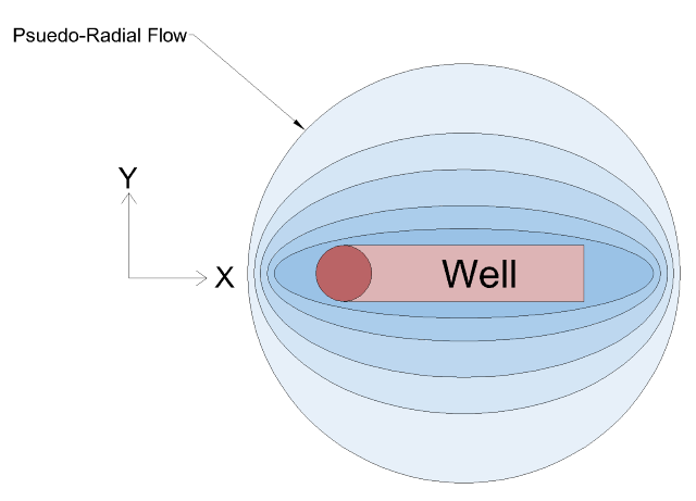
Horizontal well where elliptical flow transitions in to pseudo-radial pattern known as “Horizontal Radial Flow”
Because this is a radial flow geometry, the derivative will yield a zero slope, as seen below.

Typecurve of horizontal well as it transitions to horizontal radial flow
Time to Each Flow Phase
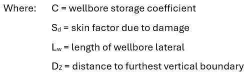
The longer a well test is run, the more flow phases you will see. If a well test is not run long enough, it may be cut off mid-way through Horizontal Linear Flow and never reach Horizontal Radial Flow. According to the SPE textbook on well testing, “Pressure Transient Testing” (Lee, Rollins, Spivey), the time to reach each flow phase can be estimated by the following equations:
Time to Vertical Radial Flow

Time to Horizontal Linear Flow

Time to Horizontal Radial Flow

Summary
The concepts of pressure transients are consistent between vertical and horizontal wells, however, they play out differently between the two. Here are the key points to remember when planning or analyzing a well test on a horizontal well:
Horizontal wells have three distinct flow phases: vertical radial, horizontal linear, and horizontal radial.
There is no way to separate horizontal and vertical permeability in the first phase (vertical radial)
At a minimum, the well test must be run long enough to reach the horizontal linear phase so that horizontal and vertical permeabilities can be separated.
If the test is run long enough to reach the horizontal radial phase, the all three permeabilities (kx, ky, and kz) can all be independently determined
Want to read more? Click here for more Well Insights.
You can also subscribe to receive Well Insights updates directly to your inbox.